INSIGHT FROM EQUIPMENT EXPERTS - What is a FOD

Foreign Object Debris (FOD) is an expression borrowed from the aeronautic world. While it normally describes foreign objects that can damage an aircraft during operation, in the API industry, it defines all objects that could accidentally fall inside a product, thereby contaminating it.

The presence of a FOD inside an API (as well as a chemical) production batch has important consequences:

  • operator safety;
  • product unconformity that can lead to reprocessing or, in the worst case, complete rejection;
  • damage to machines installed downstream of the production process.

Another complicating factor of FODs is that they are difficult to detect as they can become hidden inside the machine.

INSIGHT FROM EQUIPMENT EXPERTS - What is a FOD

FOD Sources in the API World and Vessels as Sources of FOD

Minimizing FOD release in an API plant means performing a deep analysis on how they can be generated. A multifactorial approach must be used, as different aspects of a chemical plant can be a source of debris:

  • Incorrect operating procedures
  • Inappropriate maintenance practices
  • Plant networks management: particles or elements entering process vessels from utilities plant networks (e.g. nitrogen, air, water…)
  • Cross contamination due to areas difficult to clean or poor Clean-in-Place (CIP) systems
  • Process vessel design and construction

 This paper aims to focus on the last two issues. In particular, how to design and build process vessels like:

  • Reactors and crystallizers
  • Vacuum dryers (paddle, horizontal, double cone, etc…)
  • Nutsche Filter dryers or Nutsche filters

FOD sources generated by process vessels are linked to:

  • Cross contamination, because the vessel has areas that are difficult to clean or is equipped with a poor CIP system
  • Parts that can come loose and fall off (bolts/nuts inside product area or rotating components inside the vessel)
  • Debris that can fall because of material crumbling (e.g. mechanical seal, filtering sheets, gaskets (o-rings)
FOD Sources in the API World and Vessels as Sources of FOD

Dead areas and CIP systems

Correct design in vessel shape and in the CIP system can minimize cross contamination. An excellent CIP system cannot attain the desired level of performance if the vessel is not designed in the right way (and the opposite is also true).

Aside from the functional aspects of the machine, the main target of vessel design has to be dead area minimization:

  • Nozzles located on the top head should have a conical shape
  • Horizontal surfaces are not permitted
  • Presence of a drain system
  • Surfaces in contact with the product always need to be polished (grade according to process needs)
  • Dust filters are designed with oversized dimensions, allowing for easier cleaning
  • Bellows, when used, are designed with a large pitch when compared to span

A correct approach to the CIP system design for vessels should take into consideration many parameters, not limited to the vessel itself:

  • Vessel size and shape
  • Available washing liquid features
  • Product features (if available)

Starting with these data, CIP system design normally leads to:

On the Main Vessel:

  • Spray balls (quantity depending on the machine size) on the washing heads and wall
  • Eventual additional spray balls that clean specific parts (like manholes)
  • Sprayers on sight glasses

On dust filters:

  • Spray balls (quantity and location defined according to dust filter technology and size)
  • 1 washing ring running the length of the filtering element
  • 1 dedusting system, not directly used for washing, but allowing the filtering element to be shaken and remove dry powder accumulated during the process

On Discharge Valves for solid products:

  • A spray ball for body washing
  • A system removing product from the plug seal system (normally sprayers for the seal seat and a washing ring for the plug).
Dead areas and CIP systems

Falling components and material crumbling

Minimizing falling components means minimizing parts that can potentially fall. From a design point of view, this means an extended use of welded and static components. In detail:

  • No bolts/nuts inside the process area
  • Only welded impellers
  • Only welded static spray balls
  • Only welded bellows (if required)
  • Only welded baffles (if required)

This approach, when required, totally avoids falling components under normal operating conditions, but makes vessel maintenance a little bit more difficult. In many cases, a tradeoff between these two scenarios must be made.

Material crumbling can happen on:

  • Gaskets
  • Bellows (when not made of metal)
  • Mechanical seal
  • Filtering sheets

The way to minimize this issue is:

  • Bellows only made of metallic material (the agitator, but also the discharge valve)
  • Gaskets and o-rings designed with metal-on-metal seals, hidden grooves, etc. to avoid releasing debris
Falling components and material crumbling

Mechanical seals and filtering sheet design: An important choice

Mechanical seal and filtering sheet solutions can have an important impact, since many aspects of these parts can be a potential source of FOD.

The seal can generate the release of:

  • crumbling material coming from rings
  • fluxing fluid

Both aspects can be solved using a mechanical seal lift off design. This solution, despite many advantages, can be used only if a reliable nitrogen source is available, in terms of pressure and flow. In the event that these conditions are not available, it is possible to use a dry running mechanical seal nitrogen fluxed, equipped with a sanitary tray for collecting particles released by seal rings.

Filtering media plays an important role in all aspects of FOD minimization, but in many cases, designers cannot freely choose the solution, as its design is driven by process constraints.

Multilayer sintered filtering media can be considered the best solution for FOD minimization, as it provides filtering elements:
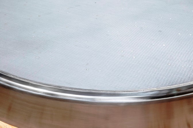
  • totally free of bolts or nuts (in some cases also directly welded on the vessel)
  • with a mechanical behavior similar to a steel sheet, allowing comparable cleaning in place procedures
  • where material crumbling is not possible.
Mechanical seals and filtering sheet design: An important choice

Testing

After design and construction, during the acceptance visit, the quality of the vessel design from an FOD point of view has to be checked. Mandatory tests should include:

  • a riboflavin test where the cleaning in place system is verified
  • draining test, to avoid any dead volume
  • gaskets and o-ring inspection for quality verification
Testing

Conclusion

Delta engineers have spent years examining the various sources of FODs in process vessels. Their vast experience in the area has helped them not only to understand what causes them, but also how to avoid them. Consequently, they have implemented solutions to the problem into the designs of various Delta machines. Avoiding FODs is not an afterthought for Delta, but an essential part of its product solutions.

Delta understands the importance of addressing FODs because of the severity of the issues that can arise as a result of them. As such, all Delta machines offer some level of protection against them.

Conclusion